ABB Totalflow I/O Addressing
Legacy vs. Register Addressing
Accessing Legacy Data Structures
Communication Methods Supported
Totalflow RTUs are capable of different modes of communication with SCADA host systems using variants of protocol messaging. Early Totalflow RTUs, manufactured in the 1980s and 1990s, use the DB1 FCU protocol. Newer Totalflow RTUs, beginning with late model Totalflow G3 models, use the DB2 FCU, DB2 Register, and DB2 Trend protocols.
Communication protocols currently supported by the VTScada Totalflow Driver include:
| Method | Comments |
|---|---|
| DB1 FCU | Not supported. |
| DB1 FCU + VCI | Not supported. |
| DB2 FCU | Supported |
| DB2 Register | Supported |
| DB2 Trend | Supported |
Addresses can be more easily configured by the SCADA administrator by using the Totalflow Address Assist feature when configuring the telemetry address.
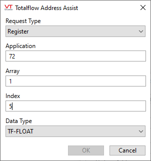
Configuration fields will vary according to the Register Type you select.
Legacy vs. Register Addressing
Totalflow RTU item addressing follows two approaches. The first is a legacy approach that can access individual data fields in "C" programming language style structures, used since the 1980s by Totalflow RTUs. Totalflow RTUs represent all types of data records as structures when using the legacy approach.
For example, a periodic flow history record has the following structure:
typedef struct
{
  TFTime  DateTime;         //Date and time
  USHORT  nSequence;        //Sequence number
  float   fpDP;             //Fixed Point Differential Pressure
  float   fpAP;             //Fixed Point Absolute Pressure
  float   fpTf;
  float   fpExtension;      //Fixed Point Extension
  float   fVolume;          //Total Volume for period (MCF)
  float   fEnergy;          //Total Energy for period
  SHORT   nFlowTime;        //Seconds flow time for period
  USHORT  nTotalLogPerTime; //Total seconds in period
  UCHAR   ucAlarms[3];      //Alarms - bit encoded
  UCHAR   ucVerCode;
  long    lArchSeq;
} ARCH_FCU_LOGPER;
Each data item in the structure has a distinct field name and a specific data type. For example, the accumulated volume for a periodic flow history record, such as fVolume , has the specific data type float.
The data field fVolume can be mapped directly to a VTScada tag such as an I/O in Analog mode, an Analog Input or Analog Status by specifying the field name and other information in the I/O address of the tag.
The second addressing approach uses a register identifier to access data items. Conceptually similar to a Modbus register address or an Emerson ROC TLP address, a register address for a Totalflow RTU provides an alias with an offset that is mapped into the specific data structures using numeric indices rather than specific data field names. Register addressing has some advantages over legacy structure addressing as registers can be queried from Totalflow RTUs in bulk for improved communication efficiency, but have the drawback of requiring a register map for the RTU, which can be dependent on the program configured in the specific RTU.
The general syntax for addressing data items in the "C" style structures within a Totalflow RTU is:
<Command Code>:<Run/Tube Number>:<Structure Field Name>
<Command Code>
Indicates to the VTScada driver which Totalflow command is to be used when reading or writing a data item in a Totalflow RTU.
<Run/Tube Number>
Indicates to the VTScada driver which integer Run/Tube number is targeted when reading or writing a data item in a Totalflow RTU.
<Structure Field Name>
Referred to as ATTRIBUTE in the address format examples that follow, this indicates to the VTScada driver which specific data field in a data structure is targeted when reading or writing a data item in a Totalflow RTU.
Sample legacy structure addresses (All DB2FCU):
AL:1:bit.19
CM:1:bit.19
DS:1:fOrificeSize { this address for example allows Read/Write }
HS:1:DAILY:fExtension
HS:1:LOGPER:fpExtension
HS:1:ALARMLOG:cMessage
HS:1:EVENT:cNewVal
HS:1:NEWEVENT:DataType
RE:1 { This is the address to write to in order to Reset Events for tube 0 }
RV:1 { This is the address to write to in order to Reset Volume for tube 0 }
DT { This is the address to writeDate Time }
The RTU vendor documents array and register numbers in their respective user manuals for various RTU models. A large amount of documentation on the numerous models of Totalflow RTU units which describes in detail the operations and register addresses is readily available on ABB's public web site or through web searches.
Often the register mapping can be defined by the Totalflow RTU programmer using the PCCU software tool also provided by the vendor.
The use of register addressing requires a register map associated with the specific program in the Totalflow RTU. As the register map can vary between RTUs, consistency in programming will make configuration of the VTScada driver simpler. In contrast, legacy structure addressing does not require a register map as the structures are predefined and consistent between different models of RTU.
The general syntax for addressing data items using register style addressing within a Totalflow RTU is:
<Command Code>:<Application>.<Array>.<Index/Register Number>[/DATA TYPE]
<Command Code>
Indicates to the VTScada driver which Totalflow command is to be used when reading or writing a data item in a Totalflow RTU. For Register addressing, the <Command Code> must be set to "RG".
<Application>
An integer value which indicates a specific application area within the Totalflow RTU that will be accessed. For example, a value of 0 (zero) is typically the "System" application.
<Array>
An integer value which indicates a specific data area within an application in the Totalflow RTU that will be accessed.
<Index>
An integer value which indicates a specific data item for a data area and application in the Totalflow RTU that will be accessed.
[/DATA TYPE]
An optional string appended to the data item address. It specifies the expected data type of the register item in the Totalflow RTU. If not specified, it defaults to TF-FLOAT (#REGTYPE_FLOAT), a 32 bit floating point value.
RG addresses have the following schema with three mandatory components and two optional ones:
RG:Application.Array.Register[/Type][/Member]
Sample addresses follow. Note that the lack of a data type implies TF-FLOAT.
Simple registers:
RG:1.2.1/TF-FLOAT , RG:1.2.1 , RG:1.6.2/TF-STR
Complex registers: (For example, registers that are structures such as Hourly or Daily records.) Note that the [/Member] component should never appear without the [/Type] part
>RG:11.250.1/TF-PER/DateTimeString, RG:11.251.1/TF-DAY/temperature }
| Register Address Data Type [/DATATYPE] Options | Internal Totalflow RTU Data Type | Description / Comments |
|---|---|---|
| TF-SWORD | #REGTYPE_INT16 | Signed 16-bit Integer |
| TF-SDWORD | #REGTYPE_INT32 | Signed 32-bit Integer |
| TF-UBYTE | #REGTYPE_BYTE | Unsigned 8-bit Integer |
| TF-UWORD | #REGTYPE_UINT16 | Unsigned 16-bit Integer |
| TF-UDWORD | #REGTYPE_UINT32 | Unsigned 32-bit Integer |
| TF-FLOAT | #REGTYPE_FLOAT | Floating Point 32-bit - default type used when optional address component [/DATA TYPE] is not specified. |
| TF-DOUBLE | #REGTYPE_DOUBLE | Floating Point 64-bit |
| TF-STR | #REGTYPE_STRING | Character String |
| TF-REG | #REGTYPE_REGISTER | |
| TF-SCT | #REGTYPE_STRUCT | |
| TF-PER | #REGTYPE_LOGPERIOD | |
| TF-DAY | #REGTYPE_DAILY | |
| TF-EVT | #REGTYPE_EVENT | |
| TF-NEVT | #REGTYPE_NEWEVENT | |
| TF-SYS | #REGTYPE_SYSTEM |
Use of the correct [/DATA TYPE] option is important for non-floating point data items. If the incorrect data type is used the read / write of the data item will result in invalid or corrupt data.
An example register address is "RG:0.8.1/TF-SWORD". Register read command, Application zero (0), array eight (8), register one (1) with a data type of TF-SWORD (16-bit integer) will read back the year number from the RTU's clock.
The general syntax for reading trend data configured within a Totalflow RTU is:
<Command Code>:<Trend File>:<Attribute>
<Command Code>
Indicates to the VTScada driver which Totalflow command is to be used when reading a data item from a Totalflow RTU. For Trend addressing, the <Command Code> must be set to "TR".
<Trend File>
Indicates to the VTScada driver which trend file is targeted when reading a data item from a Totalflow RTU.
<Attribute>
This indicates to the VTScada driver which specific data field in a data structure is targeted when reading a data item from a Totalflow RTU.
Accessing Legacy Data Structures
The "C" style data structures in a Totalflow RTU can be accessed directly based on the known field name and fixed data type of each data field. Access to the various types of structures is controlled by the Function Code specified in the I/O address.
There are several categories of Function Codes provided for mapping tag data and historical data to VTScada.
| VTScada Driver Function Code | Totalflow Function | VTScada Driver Description |
|---|---|---|
| CM | Read Current Measurement |
Used to obtain instantaneous / real-time flow data for a meter run in the RTU including real-time analysis data. This function code would, for example, be used with Analog Input or Analog Status tags. The Read Current Measurement command is capable of accessing the contents of the ARCH_FCU_ORIF_CURRENT structure for an Orifice Meter Run, the ARCH_FCU_LIQ_CURRENT structure for a Liquid Meter Run, the ARCH_FCU_TURB_CURRENT for a Pulse/PD/Turbine Meter Run and the associated ANALYSIS_RECORD structure for each meter run and access to the ARCH_FCU_HEADER structure for the meter run. When a read function is used on a VTScada input tag using the "CM" command code, the driver will use the Read Current Measurement command to acquire all the instantaneous data from the RTU for the specified meter run. No write function is supported. The Read Current Measurement command is not selective with respect to the data retrieved from the RTU. The above structures are retrieved subject to the meter run requested and the type of meter run configured in the RTU. The Read Current Measurement command has the advantage of allowing the VTScada driver to acquire all the available instantaneous measurement data from the RTU for a meter run with one request and it is simple to configure tag I/O addresses as no register mapping is required. However, as the response to the Read Current Measurement command from the RTU includes all instantaneous data, it can be less efficient with respect to communication bandwidth consumption than using Register access (refer to next section). |
| AL | Read Current Alarms |
Used to obtain instantaneous/real-time alarm information for a meter run in the RTU. This function code would, for example, be used with IO tags in the Digital mode, Digital Input or Digital Status tags. Current Alarm data is returned in the TAI_ALARM_POLL_INFO structure. The alarms are returned in the fcu_alarms[4] field which contains packed bits. When a read function is used on a VTScada input tag using the "AL" command code, the driver will use the Read Current Alarms command to acquire all the instantaneous alarm bit data from the RTU for the meter run specified. No write function is supported. Each distinct alarm is accessed by bit number for a specified meter run. |
| DS | Read Device Setup |
Used to read a meter run configuration parameter value from the RTU. This function code would be used with analog tags for read functions. The Read Device Setup command is capable of accessing the contents of the ARCH_FCU_ORIF_SETUP, the ARCH_FCU_LIQ_SETUP and the ARCH_FCU_TURB_SETUP structures and the associated ANALYSIS_RECORD structure for each meter run and access to the ARCH_FCU_HEADER structure for the meter run. The Read Device Setup command returns a large number of data fields for each meter type when performing a read function. When a read function is used on a VTScada input tag using the "DS" command code, the driver will use the Read Device Setup command to acquire the entire meter run configuration from the RTU for the specified meter run. The Read Device Setup command can be useful for monitoring / viewing meter run configuration; however the Write Device Setup command requires a number of output tags to function correctly. The RTU vendor provided tool, PCCU is better suited to maintain meter run settings. |
| DS | Write Device Setup |
Used to write meter run parameter values in the RTU. This function code would be used with analog tags for write functions. The Write Device Setup command is capable of accessing the contents of the ARCH_FCU_ORIF_SETUP, the ARCH_FCU_LIQ_SETUP and the ARCH_FCU_TURB_SETUP structures and the associated ANALYSIS_RECORD structure for each meter run. When a write function is used on a VTScada output tag using the "DS" command code, the VTScada driver will first perform a Read Device Setup command to obtain the current settings, update the changed setting and then perform a Write Device Setup command. The Write Device Setup command requires a number of output tags to function correctly. The RTU vendor provided tool, PCCU is better suited to maintain meter run and RTU settings. |
| GA | Write Gas Analysis |
Used to write new analysis data to a specified meter run in the RTU. The Write Gas Analysis command is capable of accessing the contents of the ANALYSIS_RECORD structure in each meter run of the RTU. There is no equivalent read function except for the Read Current Measurement command. When a write function is used on a VTScada output tag using the "GA" command code, the VTScada driver will first perform a Read Current Measurement command to obtain the current settings, update the changed setting in the ANALYSIS_RECORD structure and then perform a Write Gas Analysis command against the RTU for the specified meter run. |
| HS | Read History |
Used to read/upload archive records from the RTU consisting of flow data and events. History archives in the RTU are based on the contents of the ARCH_FCU_DAILY, the ARCH_FCU_LOGPER and the ARCH_FCU_EVENT structures representing daily and periodic flow records and RTU/meter event logs. The Read History command can acquire history records based on several criteria. The VTScada Totalfow driver uses a set number of days in the past to acquire historical data for a specified meter run. Daily, Periodic and Event records are acquired whenever the Read History command is used. Tags with the "HS" command code will trigger the Read History command. The update frequency for tags using this command code should not be frequent owning to the amount of data uploaded and the consumption of bandwidth. The VTScada Totalflow driver maintains context of the most recent date/time of an historical record obtained from the RTU. This context information is used to only store newer data for a meter run into the VTScada historian when historical data is collected from the RTU. |
| DT | Write Date and Time |
Used to set the clock in the RTU. The Write Date and Time command writes the current clock of computer (on which the VTScada Totalflow driver is running) to the RTU. The command is not meter run specific. No read function is available from the vendor and thus a direct read of the RTU clock is not available. However, individual clock component values can be read from the RTU using Register access. |
| RE | Write Reset Events |
Used to reset the event archives in the RTU by means of a write function. The Write Reset Events command resets the event queue in the RTU. This command is a destructive command with respect to event data meaning that when used, event data stored in the RTU will no longer be retrievable. When a write function is used on a VTScada output tag using the "RE" command code, the VTScada driver execute the Write Reset Events command against the RTU for the specified meter run. |
| RV | Write Reset Volume |
Used to reset accumulated volume counters. Some volume counters in Totalflow RTUs support this command and will reset; however, some counters in the RTU are never reset – this behavior is defined by the Totalflow RTU, not the VTScada Totalflow driver. The Write Reset Volume command is a destructive command with respect to certain accumulator data meaning that when used, accumulators stored in the RTU will be reset to 0 (zero) |
| VTScada Driver Function Code | Totalflow Function | VTScada Driver Description |
|---|---|---|
| RG | Read Registers |
Used to read a specific data item in the RTU with a particular data type. The register parameter values (Application, Array, Index) depend on the specific application configured in the RTU by the programmer using the Totalflow PCCU software tool. When a read function is used on a VTScada input tag using the "RG" command code, the VTScada driver will perform a Read Registers command to obtain the data item. The driver will coalesce multiple tag addresses into register blocks for more efficient reading where sequential Application, Array, Index values are used. ABB documentation for various RTU models and applications provides registers maps. |
| RG | Write Registers |
Used to write a specific data item in the RTU with a particular data type. The register parameter values (Application, Array, Index) depend on the specific application configured in the RTU by the programmer using the Totalflow PCCU software tool. When a write function is used on a VTScada output tag using the "RG" command code, the VTScada driver will perform a Write Registers command to set the data item. ABB documentation for various RTU models and applications provides registers maps. |
There is only one category of Function Code provided for mapping tag data and historical data to VTScada using the trend mapping approach.
| VTScada Driver Function Code | Totalflow Function | VTScada Driver Description |
|---|---|---|
| TR | Read Trends |
Used to read a specific data item in the RTU. The trend parameter values (Trend File, Attribute) depend on the specific trends configured in the RTU by the programmer using the Totalflow PCCU software tool. When a read function is used on a VTScada input tag using the "TR" command code, the VTScada driver will perform a Read Trend command to obtain the data item. The driver will coalesce multiple tag addresses into trend blocks for more efficient reading where multiple values are used. |
| VTScada Driver Tag I/O Address Format | VTScada Driver Address Description |
|---|---|
| CM:<#>:<ATTRIBUTE> |
String, where... CM specifies the use of the Read Current Measurement command followed by a colon ":" character; <#> specifies a one or two digit integer Run/Tube Number in the RTU followed by a colon ":" character; <ATTRIBUTE> is a multi-character string that specifies the Totalflow "C" style data structure field name. There are variations between each data structure returned by the Read Current Measurement command, but many field names are common amongst the different meter run types. For example, the data field fLVPVolume maintains the instantaneous accumulated volume on a meter run. The data field is common to all three meter types (Orifice, Turbine, Liquid) supported by Totalflow RTUs. A VTScada tag address specified as " CM:1:fLVPVolume " would return the current accumulated volume for meter run #1 in a Totalflow RTU, regardless of the meter type. Array fields within the data structures are not directly accessible using the CM function code. For example, in the ARCH_FCU_ORIF_CURRENT structure, the field " fLVPAlarms[3] " (an array of 3 characters) is not accessible. Alarm data must be accessed using the AL function code. The ANALYSIS_RECORD substructure of any meter run can be read using the CM function code or written using the GA function code. A VTScada tag address specified as " CM:2:fEthane " would return the current analysis setting of Ethane for meter run #2 in the RTU. A tag address of " GA:2:fEthane " would be used on an output tag to write the Ethane value for meter run #2 in the RTU. |
The available <ATTRIBUTE> settings for the Read Current Measurement command are based on the contents of the following structures (the definition each structure is are provided by the RTU vendor and documented in the Totalflow Archive Interface):
- ARCH_FCU_ORIF_CURRENT - Orifice Meter Run
- ARCH_FCU_LIQ_CURRENT - Liquid Meter Run
- ARCH_FCU_TURB_CURRENT - Pulse/PD/Turbine Meter Run
- ARCH_FCU_HEADER - General meter run information applicable to each meter type
- ANALYSIS_RECORD - Nested structure included in the structure of each meter type
Each data field in the structures outlined is available to the VTScada Totalflow driver with the exception of array based fields which contain non-character packed data such as " fLVPAlarms[3] ". Arrays containing character data can be retrieved as strings.
ARCH_FCU_ORIF_CURRENT, ANALYSIS_RECORD – these structures are retrieved for orifice meter runs and contain the instantaneous measurement data at the moment it is read from the RTU. The data includes aspects of the orifice meter run such as numerous factors for the AGA flow rate calculation, current telemetry values for meter run inputs such as differential pressure, temperature and flowing pressure, current flow rate / accumulators and gas analysis values.
typedef struct arch_orif_current_t
{   UCHAR ucDataSetID;            // Data Structure Identifier = 81
    USHORT nRecentMeasRevision;   // CCU org routines set this to - 1 for OLD meters
    float fLVPDP;                 //Differential Pressure
    float fLVPAP;                 //Absolute Pressure
    float fLVPTf;                 //Flowing Temperature
    float fLVPVolume;             //Volume (MCF) - converted by CCU
    float fLVPExt;
    float fLVPCP;
    float fLVPY;
    float fLVPFpv;
    float fLVPFw;
    float fLVPFaux;
    ULONG fLVPIrange;
    ULONG fLVPIcounts;
    float fLVPQv;
    UCHAR fLVPAlarms[3];
    ANALYSIS_RECORD LVPAnalysis;
    float fCurAP;
    float fCurDP;
    float fCurTf;
    float fCurFlow;               // MCF per day , converted by CCU
    float fYstAccVol;             // MCF
    float fCurAccVol;             // MCF
    float fCurVoltage;            // end of common vars between 1985 and 1992
                       // calculation data structures
    float fLVPFb;                 // this block of variables is used for
    float fLVPFr;                 // meters using 1985 volume calcs
    float fLVPFpb;
    float fLVPFtb;
    float fLVPFtf;
    float fLVPFg;
    float fLVPFa;
    float fLVPFip;                // this block of variables is used for
    float fLVPEv;                 // meters using 1992 volume calcs
    float fLVPCorrOrifice;
    float fLVPCorrPipe;
    float fLVPRhob;
    float fLVPQm;
    float fLVPCd;
} ARCH_FCU_ORIF_CURRENT;
typedef struct
{   float fBTU;
    float fGravity;
    float fN2;
    float fCO2;
    float fH2S;
    float fH2O;
    float fHelium;
    float fMethane;
    float fEthane;
    float fPropane;
    float fNButane;
    float fIButane;
    float fNPentane;
    float fIPentane;
    float fNHexane;
    float fNHeptane;
    float fNOctane;
    float fNNonane;
    float fNDecane;
    float fOxygen;
    float fCO;
    float fHydrogen;
    float fArgon;
} ANALYSIS_RECORD;
ARCH_FCU_TURB_SETUP, ANALYSIS_RECORD – these structures are retrieved for turbine meter runs and contain the meter run configuration data. The data includes aspects of the orifice meter run such as contract/base pressure and temperature for the AGA flow rate calculation, compressibility calculation method, meter factor, contract hour and many other settings. It is recommended that the RTU vendor’s programming software be used to maintain the configuration of Totalflow RTUs. Nonetheless, certain settings can be maintained using the VTScada Totalflow driver. For example, gas analysis components.
The ANALYSIS_RECORD structure is identical for all meter run types.
typedef struct
{
  UCHAR   DataSetID;             // Data Structure Identifier = 82
  USHORT  nDeviceSetupRevision; // CCU org routines set this to -1 for OLD meters
  BOOL1   bPasswordMode;
  USHORT  nLastLoginTag;
  BOOL1   bCheckSecCode;
  UCHAR   ucPrimaryElement;
  USHORT  nPrimaryElementMask;
  UCHAR   ucVolCalcMethod;
  USHORT  nVolCalcMethodMask;
  UCHAR   ucReportUnits;
  USHORT  nReportUnitsMask;
  UCHAR   ucCalcUnits;
  USHORT  nCalcUnitsMask;
  UCHAR   ucZMethod;
  USHORT  nZMethodMask;
  UCHAR   ucDispRate;
  UCHAR   ucCdisp;
  UCHAR   ucUdisp;
  ULONG   ulVolumeLogPeriod;
  USHORT  nVolumeCalcPeriod;
  USHORT  nFlowPeriod;
  UCHAR   ucContractHour;
  float   fTBase;
  float   fPBase;
  float   fRsph;
  float   fViscosity;
  float   fFt;
  float   fFp;
  float   fBarop;
  float   fFaux;
  BOOL1   bUseFtc;
  BOOL1   bUseFpc;
  BOOL1   bUseS;
  BOOL1   bUseFaux;
  float   fAPLowLimit;
  float   fAPHiLimit;
  float   fAPLowCalibration;
  float   fAPMidLowCalibration;
  float   fAPMidCalibration;
  float   fAPMidHiCalibration;
  float   fAPHiCalibration;
  BOOL1   bUseMeasuredAP;
  float   fFixedAP;
  float   fK;
  BOOL1   bRTDInstalled;
  BOOL1   bUseMeasTemp;
  float   fFixedTf;
  float   fTempBias;
  float   fTfLowLimit;
  float   fTfHiLimit;
  float   fFlowLowLimit;
  float   fFlowHiLimit;
  float   fAcfLowLimit;
  float   fAcfHiLimit;
  BOOL1   bLCContact1;
  BOOL1   bAPLowContact1;
  BOOL1   bAPHighContact1;
  BOOL1   bACFLowContact1;
  BOOL1   bACFHighContact1;
  BOOL1   bRemSenseContact1;
  BOOL1   bVolSetpointContact1;
  float   fVolumeSetpoint;
  BOOL1   bAutoResetContact1;
  BOOL1   bStreamAttached;
  ULONG   ulStreamID;
  BOOL1   bFixedAxOnError;
  BOOL1   bFirstAnalysis;
  ANALYSIS_RECORD FixedAnalysis;
  BOOL1   bTfLowContact1;
  BOOL1   bTfHighContact1;
  BOOL1   bFlowLowContact1;
  BOOL1   bFlowHighContact1;
  BOOL1   bLCContact2;
  BOOL1   bACFLowContact2;
  BOOL1   bACFHighContact2;
  BOOL1   bAPLowContact2;
  BOOL1   bAPHighContact2;
  BOOL1   bRemSenseContact2;
  BOOL1   bVolSetpointContact2;
  float   fVolumeSetpoint2;
  BOOL1   bAutoResetContact2;
  BOOL1   bTfLowContact2;
  BOOL1   bTfHighContact2;
  BOOL1   bFlowLowContact2;
  BOOL1   bFlowHighContact2;
  BOOL1   bHVSelect;
} ARCH_FCU_TURB_SETUP;
ARCH_FCU_LIQ_SETUP, ANALYSIS_RECORD – these structures are retrieved for liquid meter runs and contain the meter run configuration data. The data includes aspects of the orifice meter run such as contract/base pressure and temperature for the AGA flow rate calculation, low flow cutoff, compressibility calculation method, meter factor, contract hour and many other settings. It is recommended that the RTU vendor’s programming software be used to maintain the configuration of Totalflow RTUs. Nonetheless, certain settings can be maintained using the VTScada Totalflow driver. (For example, gas analysis components.)
The ANALYSIS_RECORD structure is identical for all meter run types.
typedef struct
{
  UCHAR DataSetID;          // Data Structure Identifier = undefined
  USHORT nCurrMeasRevision; // CCU org routines set this to -1 for OLD meters
  BOOL1 bPasswordMode;
  USHORT nLastLoginTag;
  BOOL1 bCheckSecCode;
  UCHAR ucBaudRate;
  UCHAR ucParity;
  UCHAR ucStopBits;
  UCHAR ucDataBits;
  UCHAR ucPrimaryElement;
  USHORT nPrimaryElementMask;
  UCHAR ucVolCalcMethod;
  USHORT nVolCalcMethodMask;
  UCHAR ucReportUnits;
  USHORT nReportUnitsMask;
  UCHAR ucCalcUnits;
  USHORT nCalcUnitsMask;
  ULONG ulVolumeLogPeriod;
  USHORT nVolumeCalcPeriod;
  UCHAR ucContractHour;
  float fOrificeSize;
  float fPipeSize;
  float fViscosity;
  BOOL1 bMonelOrifice;
  float fZeroCutoff;
  BOOL1 bUseFb;
  BOOL1 bUseFr;
  BOOL1 bUseFg;
  BOOL1 bUseFa;
  BOOL1 bUseFaux;
  float fFaux;
  float fK0;
  float fE;
  float fVcfK0;
  float fVcfK1;
  float fVcfK2;
  float fLiqGravity;
  BOOL1 bAPPresent;
  UCHAR ucFlowUnits;
  UCHAR ucDailyUnits;
  UCHAR ucHourlyUnits;
  UCHAR ucLiquidType;
  float fDPLowLimit;
  float fDPHiLimit;
  float fDPLowCalibration;
  float fDPMidLowCalibration;
  float fDPMidCalibration;
  float fDPMidHiCalibration;
  float fDPHiCalibration;
  float fAPLowLimit;
  float fAPHiLimit;
  float fAPLowCalibration;
  float fAPMidLowCalibration;
  float fAPMidCalibration;
  float fAPMidHiCalibration;
  float fAPHiCalibration;
  float fTfLowLimit;
  float fTfHiLimit;
  BOOL1 bRTDInstalled;
  BOOL1 bUseMeasTemp;
  float fFixedTf;
  float fTempBias;
  BOOL1 bLCContact1;
  BOOL1 bDPLowContact1;
  BOOL1 bDPHighContact1;
  BOOL1 bAPLowContact1;
  BOOL1 bAPHighContact1;
  BOOL1 bRemSenseContact1;
  BOOL1 bAutoResetContact1;
  BOOL1 bVolSetpointContact1;
  float fVolumeSetpoint1;
  ANALYSIS_RECORD FixedAnalysis;
    // extension of record for new database
  float fFlowLowLimit;     // Flow Rate Low Limit
  float fFlowHighLimit;    // Flow Rate High Limit
  BOOL1 bTfLowContact1;    // Trip contact on TF low
  BOOL1 bTfHighContact1;   // Trip contact on TF high
  BOOL1 bFlowLowContact1;  // Trip contact on FlowRate low
  BOOL1 bFlowHighContact1; // Trip contact on FlowRate high
  BOOL1 bLCContact2;
  BOOL1 bDPLowContact2;
  BOOL1 bDPHighContact2;
  BOOL1 bAPLowContact2;
  BOOL1 bAPHighContact2;
  BOOL1 bRemSenseContact2;
  BOOL1 bAutoResetContact2;
  BOOL1 bVolSetpointContact2;
  float fVolumeSetpoint2;
  BOOL1 bTfLowContact2;    // Trip contact on TF low
  BOOL1 bTfHighContact2;   // Trip contact on TF high
  BOOL1 bFlowLowContact2;  // Trip contact on FlowRate low
  BOOL1 bFlowHighContact2; // Trip contact on FlowRate high
} ARCH_FCU_LIQ_SETUP;
This type of address should only be used on output only tags. Gas Analysis values can be read using Device Setup, Current Measurement, and Read Register addresses.
| VTScada Driver Tag I/O Address Format | VTScada Driver Address Description |
|---|---|
| GA:<#>:<ATTRIBUTE> |
String where... GA specifies the use of the Write Gas Analysis command followed by a colon ":" character; <#> specifies a one or two digit integer Run/Tube Number in the RTU followed by a colon ":" character; <ATTRIBUTE> is a multi-character string that specifies the Totalflow "C" style data structure field name. The ANALYSIS_RECORD substructure of any meter run can be written using the GA function code. A VTScada tag address specified as " GA:2:fEthane " would write the current analysis setting of Ethane for meter run #2 in the RTU from the output tag value. Note: a Read Current Measurement command is used to read the current settings for the meter run prior to the write function. |
The available <ATTRIBUTE> settings for the Write Gas Analysis command are based on the contents of the following structures (the definition each structure is provided by the RTU vendor and documented in the Totalflow Archive Interface)
typedef struct
{ float fBTU;
  float fGravity;
  float fN2;
  float fCO2;
  float fH2S;
  float fH2O;
  float fHelium;
  float fMethane;
  float fEthane;
  float fPropane;
  float fNButane;
  float fIButane;
  float fNPentane;
  float fIPentane;
  float fNHexane;
  float fNHeptane;
  float fNOctane;
  float fNNonane;
  float fNDecane;
  float fOxygen;
  float fCO;
  float fHydrogen;
  float fArgon;
} ANALYSIS_RECORD;
| VTScada Driver Tag I/O Address Format | VTScada Driver Address Description |
| HS:<#>:<ATTRIBUTE> |
String, where... HS specifies the use of the Read History By Days command followed by a colon ":" character; <#> specifies a one or two digit integer Run/Tube Number in the RTU followed by a colon ":" character; <ATTRIBUTE> is a multi-character string that specifies the Totalflow "C" style data structure field name. T here are variations between each data structure returned by the Read History command, depending on the historical record type being accessed. The records do not vary by meter run type. A few field names are common between the Daily and Periodic flow records. For example, the " fVolume " field is common to all meters for flow records. A VTScada tag address specified as " HS:3:DAILY:fVolume " would return the most recent contract day accumulated flow on meter run #3 in a Totalflow RTU, regardless of the meter type. Similarly, an address of " HS:2:LOGPER:fVolume " would access the Periodic Archive records for run 2 and the "Total Volume for period (MCF)". The period is dependent on the specific RTU settings. Array fields within the data structures are not directly accessible using the HS function code. Possible strings: DAILY, LOGPER, ALARMLOG, EVENT, NEWEVENT |
The available <ATTRIBUTE> settings for the Read History command are based on the contents of the following structures (the definition each structure is are provided by the RTU vendor and documented in the Totalflow Archive Interface):
- ARCH_FCU_DAILY - Daily flow record
- ARCH_FCU_LOGPER - Periodic flow record (typically hourly)
- ARCH_FCU_ALARMLOG - Alarms log record
- ARCH_FCU_EVENT - RTU/Meter Run event record
- ARCH_FCU_NEW_EVENT - RTU/Meter Run new event record
- ARCH_FCU_HEADER - General meter run information applicable to each meter type
typedef struct {
  BYTE       bVerCode;
  BYTE       bDirection;
  UINT16     nSequence;
  UINT16     nDataType;
  INT16      nFormat;
  __time64_t time;
  BYTE       Value[8];
  BYTE       Limit[8];
  char       cMessage[65];
  BYTE       spare;
} ARCH_FCU_ALARMLOG;
typedef struct
{
  TFTime DateTime;        //Date and time
  USHORT nSequence;       //Sequence number;
  USHORT nLastEvtSeq;     //Last Event Sequence number
  USHORT nLPStartSeq;     //Log Period Starting Sequence;
  USHORT nLPEndSeq;       //Log Period End sequence
  UCHAR ucContractHour;   //Contract hour
  float fExtension;       //Average Extension
  float fVolume;          //Total Volume for day (MCF)
  float fEnergy;          //Total Energy for day
  ULONG ulFlowTime;       //Flow seconds for the day
  ULONG ulBackFlow;       //Back flow seconds for the day
  ULONG ulTotalDailyTime; //Log period seconds
  UCHAR ucAlarms[3];      //Alarms - bit encoded
  float fpAP;             //Average AP
  float fMinAP;           //Minimum AP
  float fMaxAP;           //Maximum AP
  float fPerctAPLow;      //Percent of day below low limit
  float fPerctAPHigh;     //Percent of day above high limit
  float fpDP;             //Average DP
  float fMinDP;           //Minimum DP
  float fMaxDP;           //Maximum DP
  float fPerctDPLow;      //Percent of day below low limit
  float fPerctDPHigh;     //Percent of day above high limit
  float fpTf;             //Average Tf
  float fMinTf;           //Minimum Tf
  float fMaxTf;           //Maximum Tf
  float fPerctTfLow;      //Percent of day below low limit
  float fPerctTfHigh;     //Percent of day above high limit
  UCHAR ucVerCode;        //Verification code
  long lArchSeq;          //Archive Sequence number
  long lArchLPStart;      //Archive Log Period Start
  long lArchLPEnd;        //Archive Log Period End
} ARCH_FCU_DAILY;
typedef struct
{
  TFTime DateTime;    //Date and time
  USHORT nSequence;   //Sequence number
  float fpDP;         //Fixed Point Differential Pressure
  float fpAP;         //Fixed Point Absolute Pressure
  float fpTf;
  float fpExtension;  //Fixed Point Extension
  float fVolume;      //Total Volume for period (MCF)
  float fEnergy;      //Total Energy for period
  SHORT nFlowTime;    //Seconds flow time for period
  USHORT nTotalLogPerTime; //Total seconds in period
  UCHAR ucAlarms[3];  //Alarms - bit encoded
  UCHAR ucVerCode;
  long lArchSeq;
} ARCH_FCU_LOGPER;
typedef struct
{
  TFTime DateTime;  // Date and time
  UCHAR ucFlags;    // flags byte (4 lsb - fcu; 4 msb - ccu)
  USHORT nSequence; // sequence number
  USHORT nCode;     // event code
  EVENT_VALUE val;  // event old/new value
  UCHAR ucVerCode;  // verification code
  long lArchSeq;
} ARCH_FCU_EVENT;
typedef struct
{
  __time32_t Time;
  BYTE Flags;
  UINT16 SeqNumber;
  UINT16 eCode;
  BYTE OldValue1[4];
  BYTE NewValue1[4];
  BYTE vCode1;
  BYTE revision;
  BYTE DataType;
  BYTE UnitGroupID;
  char OperatorName[32];
  char PointName[65];
  char OldValue2[65];
  char NewValue2[65];
  BYTE vCode2;
} ARCH_FCU_NEW_EVENT;
