Enron Modbus I/O Addressing
Standard Values
For standard reads and writes, the address can be entered directly into the address field. Unlike with the standard Modbus driver there is no need to indicate the data type (e.g. /FLOAT) because each data type has its own predefined address range.
| Register Numbers | Type | Table Name |
|---|---|---|
| 1001-1999 | Read-Write | Boolean variables |
| 3001-3999 | Read-Write | 16 bit Short integer variables |
| 5001-5999 | Read-Write | 32 bit Long integer variables |
| 7001-7999* | Read-Write | 32 bit Floating point variables |
*Many devices allow floating point addresses above 7999.
History Logs
Note: The history logs can only be read in conjunction with an Enron History Log tag. See the Enron History Log Tag section for details on both the tag and the history storage methodology.
Analog Status tags, which store history information, should use the address structure:
HL:x:y
where x is the address of the history log (usually 701 or 702) and y is the variable's position in the returned history record (beginning with 0).
Alarm/Event Logs
An Enron Modbus device has a single log where both alarm and event information is stored. It should be noted that the alarms logged here are internal to the device and to the device's flow calculations, and as such are not necessarily related to alarms in VTScada.
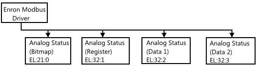
Along with the timestamp, four pieces of information are returned as part of each event/alarm. Each of these pieces of information should be captured in its own analog status tag with the address:
EL:x:y
where x is the address of the alarm log (usually 32) and y is a value between 0-3 based on the chart following.
| Address Index | Description | Comments |
|---|---|---|
| 0 | Bitmap | Group of flags describing the event/alarm (see following) |
| 1 | Register | Register that was changed/that triggered the alarm |
| 2 | Data1 | Previous value (event) or current value (alarm) |
| 3 | Data2 | Current value (event) or not used (alarm) |
The Bitmap is a group of flags whose meanings change based on whether the record is an event or an alarm. Of particular importance is bit 9, which is always a 1 for an event and a 0 for an alarm.
| Bit Number | Alarm Map | Operator Event Map |
|---|---|---|
| 0 | unassigned | Fixed Value |
| 1 | unassigned | Zero Scale |
| 2 | unassigned | Full Scale |
| 3 | unassigned | Operator Entry Work Value |
| 4 | unassigned | Boolean Fixed Bit |
| 5 | unassigned | Fixed/Variable Flag |
| 6 | unassigned | Table Entry Change |
| 7 | unassigned | System Command Change |
| 8 | unassigned | unassigned |
| 9 | Operator Change Event Bit (Always 0) | Operator Change Event Bit (Always 1) |
| 10 | Lo-Lo Limit | Lo-Lo Limit |
| 11 | Lo Limit | Lo Limit |
| 12 | Hi Limit | Hi Limit |
| 13 | Hi-Hi Limit | Hi-Hi Limit |
| 14 | Rate of Change Limit | Rate of Change Limit |
| 15 | Set/Reset Alarm (1 = set, 0 = reset) | unassigned |
The diagram following details the tag setup. Contrasting this with the diagram of the historical log, you can see that no intermediary tag is necessary between the driver and the status tags. However, you may still choose to add a context tag to group the four analog status tags together.
Omni Flow Computers
The prefix of S8: can be used to denote that an address will return an 8 character string. For example, S8:4001 will interpret the data from address 4001 as an 8 character string.
You can read bit values from registers and history log entries by using a / or \ followed by the bit number to read.
Note that bit writes for non-boolean registers are NOT supported.
