Mitsubishi Driver
Provides support for the Mitsubishi iQ-R and Q series of PLC's.
Communication uses theMELSEC protocol, which is a Mitsubishi-specific protocol that can be used to speak to their various models of PLCs. It consists of various frame types based on the PLC and communication type (Ethernet or serial), and supports two different encodings: Binary and ASCII. Binary is the more efficient encoding, but ASCII can be more readable to some packet monitoring tools.
Support is provided for the following frame and format type combinations:
| PLC Series | CPU Type | Frame Type |
Format Type | Communication Mode |
|---|---|---|---|---|
| iQR | n/a | 3E | n/a |
Binary ASCII |
| 4E | n/a |
Binary ASCII |
||
| 2C |
Format 1 Format 2 Format 4 |
n/a |
||
| 3C |
Format 1 Format 2 Format 4 |
n/a | ||
| 4C |
Format 1 Format 2 Format 4 Format 5 |
n/a | ||
| Q |
Universal Model QCPU High Performance Model QCPU |
3E | n/a |
Binary ASCII |
| 4E | n/a |
Binary ASCII |
||
| 2C |
Format 1 Format 2 Format 4 |
n/a |
||
| 3C |
Format 1 Format 2 Format 4 |
n/a |
||
| 4C |
Format 1 Format 2 Format 4 Format 5 |
n/a |
Format Type 3 is not currently supported.
The driver supports batch read and writes for device data using device-level commands.
The ID tab of every tag includes the same common elements: Name, Area, Description, and Help ID.
Name:
Uniquely identifies each tag in the application. If the tag is a child of another, the parent names will be displayed in a separate area before the name field.
You may right-click on the tag's name to add or remove a conditional start expression.
Area
The area field is used to group similar tags together. By defining an area, you make it possible to:
- Filter for particular tag groups when searching in the tag browser
- Link dial-out alarm rosters to Alarm tags having a particular area
- Limit the number of tags loaded upon startup.
- Filter the alarm display to show only certain areas.
- Filter tag selection by area when building reports
When working with Parent-Child tag structures, the area property of all child tags will automatically match the configured area of a parent. Naturally, you can change any tag's area as required. In the case of a child tag, the field background will turn yellow to indicate that you have applied an override. (Orange in the case of user-defined types. Refer to Configuration Field Colors)
To use the area field effectively, you might consider setting the same Area for each I/O driver and its related I/O tags to group all the tags representing the equipment processes installed at each I/O device. You might also consider naming the Area property for the physical location of the tag (i.e. a station or name of a landmark near the location of the I/O device). For serial port or Roster tags, you might configure the Area property according to the purpose of each tag, such as System or Communications.
You may define as many areas as you wish and you may leave the area blank for some tags (note that for Modem tags that are to be used with the Alarm Notification System, it is actually required that the area field be left blank).
To define a new area, type the name in the field. It will immediately be added. To use an existing area, use the drop-down list feature. Re-typing an existing area name is not recommended since a typo or misspelling will result in a second area being created.
There is no tool to remove an area name from VTScada since such a tool is unnecessary. An area definition will exist as long as any tag uses it and will stop existing when no tag uses it (following the next re-start).
Description
Tag names tend to be brief. The description field provides a way to give each tag a human-friendly note describing its purpose. While not mandatory, the description is highly recommended.
Tag descriptions are displayed in the tag browser, in the list of tags to be selected for a report and also on-screen when the operator holds the pointer over the tag’s widget. For installations that use the Alarm Notification System, the description will be spoken when identifying the tag that caused the alarm.
The description field will store up to 65,500 characters, but this will exceed the practical limits of what can be displayed on-screen.
This note is relevant only to those with a multilingual user interface:
When editing any textual parameter (description, area, engineering units...) always work in the phrase editor. Any changes made directly to the textual parameter will result in a new phrase being created rather than the existing phrase being changed.
In a unilingual application this makes no difference, but in a multilingual application it is regarded as poor practice.
Help Search Key
Used only by those who have created their own CHM-format context sensitive help files to accompany their application.
Server List
Select (or create) a named server list.
Mitsubishi Driver tag properties: Options tab
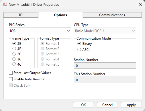
Refer to the table at the beginning of this topic for supported combinations of PLC Series, Frame Type and Format Type.
PLC Series
Select between the iQR and the Q series of PLC.
CPU Type
Enabled only for the Q series of PLC. Select between the following:
- Basic Model QCPU
- Universal Model QCPU
- High Performance Model QCPU
Frame Type
Choose between 3E or 4E, 2C, 3C or 4C as appropriate for your device.
Format Type
Only supported for serial frames. Available format types (from 1 through 5) vary depending on the selection of Frame Type.
Format type 3 is not currently supported.
Communication Mode
Only supported for ethernet frames. Choose between Binary or ASCII as appropriate for your device. Binary is the more data-efficient option if a choice is available.
Check Sum
Only supported for serial frames. Choose whether the driver should examine the check sum code.
Station Number
Only supported for serial frames. Specify the station to be connected from an external device.
This Station Number
Only supported for serial frames. Specify this when more than one external device (m stations) and more than one C24s (n stations) are connected with the multidrop connection. Specify the fixed value (00H) for any cases other than multidrop connection in the form, m:n.
Store Last Output Values
When selected, the driver will maintain a record of the last value written to each output address. This may be useful in at least two situations:
- For hardware that does not maintain its state during a power loss and must be restored to that state when re-started.
- When failed hardware is replaced by a new device and you would like to start that device with the values last written to the old one.
If the last output values are stored, they may be re-written by either of two methods:
- Automatically, when communication is restored to the device.
- Manually by way of a button press. See, Rewrite Outputs Widget for details.
Changing this value from selected to deselected will cause all stored values to be erased immediately.
Enable Auto Rewrite
If selected, the Store Last Output Values option will also be activated. This option causes the driver to rewrite the last value written to each output, in the event that communications are lost and then restored.
Use this option only if you are certain that you want the last values to be rewritten automatically after an interruption in driver communications.
Mitsubishi Driver tag properties: Communications tab
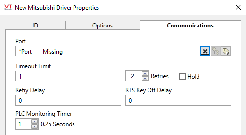
Port
The port tag through which this driver communicates to a device, usually either a serial port tag or a TCP/IP tag.
Timeout Limit
Set the receiver time-out limit in seconds or fractions of a second. This is the length of time that this driver should wait for a reply from the PLC or RTU.
Retries
The number of times to retry a message before declaring an error.
Use only if the driver is connected to a device that uses a serial port or a UDP/IP port that is configured to be polled. When connected directly to a device using TCP/IP, this value should normally be set to 0 since TCP/IP is a guaranteed message delivery protocol.
For unreliable communications, such as radio, set to 3 or 4.
Hold
Select this to have I/O tags attached to the driver hold their last value in the event of a communication failure. If not selected, tags will have their value set to invalid on a communication failure.
Retry Delay
Sets the length of time (in seconds or fractions of a second) that the driver will wait between attempts to repeat a transmission of data if the previous attempt(s) have failed.
By default, the Retry Delay field is set to 0 (indicating that there should be no delay between retry attempts).
RTS Key Off Delay
The length of time (in seconds) that this device will wait before dropping RTS at the end of a data transmission.
PLC Monitoring Timer
Measured in multiples of 0.25 seconds. This is the time to wait for the PLC to process messages. Set to 0 for "indefinite".
The following widgets are available to display information about your tags:
Mitsubishi Driver Communication Messages Dialog
Mitsubishi Driver Statistics Dialog
