Opto 22 Mux Driver
The Opto 22 Mux Driver is designed to communicate with Opto22™ B1, B2, B4 and B5 brain boards. Communications to the brain boards can be via an RS485 serial link for B1 and B2 brain boards or the Pamux™ bus using an ISA bus adapter card for B4 and B5 brain boards
The addresses available for your I/O tags are configured within this driver tag. An address selection is available, but rather than being a dialog to be opened, it is a drop-down list within the I/O tag, showing all available addresses as configured within the driver.
The ID tab of every tag includes the same common elements: Name, Area, Description, and Help ID.
Name:
Uniquely identifies each tag in the application. If the tag is a child of another, the parent names will be displayed in a separate area before the name field.
You may right-click on the tag's name to add or remove a conditional start expression.
Area
The area field is used to group similar tags together. By defining an area, you make it possible to:
- Filter for particular tag groups when searching in the tag browser
- Link dial-out alarm rosters to Alarm tags having a particular area
- Limit the number of tags loaded upon startup.
- Filter the alarm display to show only certain areas.
- Filter tag selection by area when building reports
When working with Parent-Child tag structures, the area property of all child tags will automatically match the configured area of a parent. Naturally, you can change any tag's area as required. In the case of a child tag, the field background will turn yellow to indicate that you have applied an override. (Orange in the case of user-defined types. Refer to Configuration Field Colors)
To use the area field effectively, you might consider setting the same Area for each I/O driver and its related I/O tags to group all the tags representing the equipment processes installed at each I/O device. You might also consider naming the Area property for the physical location of the tag (i.e. a station or name of a landmark near the location of the I/O device). For serial port or Roster tags, you might configure the Area property according to the purpose of each tag, such as System or Communications.
You may define as many areas as you wish and you may leave the area blank for some tags (note that for Modem tags that are to be used with the Alarm Notification System, it is actually required that the area field be left blank).
To define a new area, type the name in the field. It will immediately be added. To use an existing area, use the drop-down list feature. Re-typing an existing area name is not recommended since a typo or misspelling will result in a second area being created.
There is no tool to remove an area name from VTScada since such a tool is unnecessary. An area definition will exist as long as any tag uses it and will stop existing when no tag uses it (following the next re-start).
Description
Tag names tend to be brief. The description field provides a way to give each tag a human-friendly note describing its purpose. While not mandatory, the description is highly recommended.
Tag descriptions are displayed in the tag browser, in the list of tags to be selected for a report and also on-screen when the operator holds the pointer over the tag’s widget. For installations that use the Alarm Notification System, the description will be spoken when identifying the tag that caused the alarm.
The description field will store up to 65,500 characters, but this will exceed the practical limits of what can be displayed on-screen.
This note is relevant only to those with a multilingual user interface:
When editing any textual parameter (description, area, engineering units...) always work in the phrase editor. Any changes made directly to the textual parameter will result in a new phrase being created rather than the existing phrase being changed.
In a unilingual application this makes no difference, but in a multilingual application it is regarded as poor practice.
Help Search Key
Used only by those who have created their own CHM-format context sensitive help files to accompany their application.
Server List
Select (or create) a named server list.
Opto 22 Mux properties, Serial tab
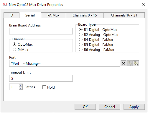
Brain Board Address
The brain board address.
Board Type
Choices as shown.
Channel
Choices as indicated.
Port
Select the serial port tag used to access the physical Opto 22 device.
Retries
The number of times to retry a message before declaring an error.
Use only if the driver is connected to a device that uses a serial port or a UDP/IP port that is configured to be polled. When connected directly to a device using TCP/IP, this value should normally be set to 0 since TCP/IP is a guaranteed message delivery protocol.
For unreliable communications, such as radio, set to 3 or 4.
Hold
Select this to have I/O tags attached to the driver hold their last value in the event of a communication failure. If not selected, tags will have their value set to invalid on a communication failure.
Time-Out Limit
Set the receiver time-out limit in seconds or fractions of a second. This is the length of time that this driver should wait for a reply from the PLC or RTU.
Opto 22 Mux properties, PA Mux tab
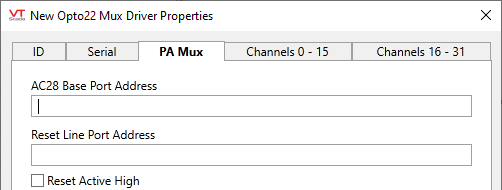
AC28 Base Port Address
AC28 adapter card base address. Only required for Pamux protocol
Reset Line Port Address
Port address for Pamux reset port. Only required for Pamux protocol.
Reset Active High
If set the brain board reset is active high. Only required for Pamux protocol.
Opto 22 Mux properties, Channels 0 - 15 tab
This tab allows for the configuration of the individual channels of the Opto 22 device, 0 through 15.
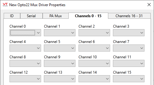
Channel x:
This is configuration of the individual channels of the Opto 22 device. Options include:
- None = No module present
- DO = Digital Output
- DI = Digital Input
- AI = Analog Input
- AO = Analog Output
- ICTD = ICTD Probe AD4 Module
- RTD 10 = 10 Ohm RTD AD14T Module
- RTD 100 = 100 Ohm RTD AD10T Module
- TC-J = Type J Thermocouple AD5/AD5T Module
- TC-K = Type K Thermocouple AD8/AD8T Module
- TC-R = Type R Thermocouple AD17T Module
- TC-S = Type S Thermocouple AD17T Module
- TC-T = Type T Thermocouple AD18T Module
- TC-E = Type E Thermocouple AD19T Module
Opto 22 Mux properties, Channels 16 - 31 tab
This tab allows for the configuration of the individual channels of the Opto 22 device, 16 through 31.
Refer to the description of the previous tab for details.
The following widgets are available to display information about your tags:
