Serial Port Tags
Not counted towards your tag license limit.
with TCP/IP ports are a viable option when RS-232 cards are not available.)
Reference Notes:
Monitor drivers, not ports. A port tag has a value only on the server that is communicating with hardware and will be blank on all other servers. The value of a port tag is not synchronized across all workstations. (Unlike I/O and driver tags.) If the alarm server and I/O servers are different machines, an alarm on a port tag will not activate. Do not attach an alarm to any port tag.
A port tag widget drawn on a page represents only state of the port on the local machine.
The transmit and receive buffer lengths are fixed at 16384 bytes.
The Data Transmit Ready (DTR) parameter of the serial port is fixed at 1
Serial port tags may use the same port for different purposes on two different PCs. This is achieved by the re-use of serial ports on backup machines in a multi-server application![]() An application that simultaneously runs on two or more computers. Usually configured with at least one primary server and one backup server..
An application that simultaneously runs on two or more computers. Usually configured with at least one primary server and one backup server..
The application property, SerialShareSemaphore has been marked as deprecated. In the unusual event that you have multiple devices attempting to use the same channel at the same time across multiple ports, you might consider adding Comm Link Sequencer Tags to serialize requests.
A valid Serial Port Tag will have one of two values:
- 0 (zero) indicates a good connection.
- 2 indicates that the port is not available.
Comm Link Sequencer Tags - Serialize requests for the same communication channel across ports.
Modem Tags - Details about configuring Modem tags.
SerPortDisconnectDelay - Port Sharing: Multiple drivers can share a Serial Port tag when it is in ‘serial’ mode.
The ID tab of every tag includes the same common elements: Name, Area, Description, and Help ID.
Name:
Uniquely identifies each tag in the application. If the tag is a child of another, the parent names will be displayed in a separate area before the name field.
You may right-click on the tag's name to add or remove a conditional start expression.
Area
The area field is used to group similar tags together. By defining an area, you make it possible to:
- Filter for particular tag groups when searching in the tag browser
- Link dial-out alarm rosters to Alarm tags having a particular area
- Limit the number of tags loaded upon startup.
- Filter the alarm display to show only certain areas.
- Filter tag selection by area when building reports
When working with Parent-Child tag structures, the area property of all child tags will automatically match the configured area of a parent. Naturally, you can change any tag's area as required. In the case of a child tag, the field background will turn yellow to indicate that you have applied an override. (Orange in the case of user-defined types. Refer to Configuration Field Colors)
To use the area field effectively, you might consider setting the same Area for each I/O driver and its related I/O tags to group all the tags representing the equipment processes installed at each I/O device. You might also consider naming the Area property for the physical location of the tag (i.e. a station or name of a landmark near the location of the I/O device). For serial port or Roster tags, you might configure the Area property according to the purpose of each tag, such as System or Communications.
You may define as many areas as you wish and you may leave the area blank for some tags (note that for Modem tags that are to be used with the Alarm Notification System, it is actually required that the area field be left blank).
To define a new area, type the name in the field. It will immediately be added. To use an existing area, use the drop-down list feature. Re-typing an existing area name is not recommended since a typo or misspelling will result in a second area being created.
There is no tool to remove an area name from VTScada since such a tool is unnecessary. An area definition will exist as long as any tag uses it and will stop existing when no tag uses it (following the next re-start).
Description
Tag names tend to be brief. The description field provides a way to give each tag a human-friendly note describing its purpose. While not mandatory, the description is highly recommended.
Tag descriptions are displayed in the tag browser, in the list of tags to be selected for a report and also on-screen when the operator holds the pointer over the tag’s widget. For installations that use the Alarm Notification System, the description will be spoken when identifying the tag that caused the alarm.
The description field will store up to 65,500 characters, but this will exceed the practical limits of what can be displayed on-screen.
This note is relevant only to those with a multilingual user interface:
When editing any textual parameter (description, area, engineering units...) always work in the phrase editor. Any changes made directly to the textual parameter will result in a new phrase being created rather than the existing phrase being changed.
In a unilingual application this makes no difference, but in a multilingual application it is regarded as poor practice.
Help Search Key
Used only by those who have created their own CHM-format context sensitive help files to accompany their application.
Serial Port properties Settings tab
Use the settings tab to configure the tag for the communication parameters required by your hardware. The default settings for data bits, speed and parity are those which are most commonly in use.
When Use Modem is not selected, you must specify the COM port number in use. If Use Modem is selected, the Port Number field will be disabled and the Phone Number field enabled.
The required values for all the configuration options should be available from the specification provided with the hardware device connected to your serial port.

Use Modem
Provides control over whether a modem or a serial port is to be used.
This check box must be selected, and a remote phone number phone number provided if the driver attached to this port is to be a modem tag.
When the Use Modem check box is selected, the Phone Number and Modem Initialization fields will be enabled.
Port Number
Used to set the number of the serial port that is to be used. The corresponding serial port number must be configured in the Ports dialog box of the Windows Control Panel. The value should match your port number and be between 1 and 4096.
If the Use Modem check box is selected, the Port Number field will be disabled and the Phone Number and Modem Initialization fields will be enabled.
Phone Number
When a modem is to be used, fill in this field with the phone number that the modem must call to reach the remote system. Supply all the digits including area code, etc. Do not include spaces.
If the Use Modem check box is not selected, the Phone Number field will be disabled.
Modem Initialization String
Used only if your modem requires a customized initialization string. In most situations, you will leave this field blank. If configured, any initialization string must be prefixed by "AT". Note that the initialization string will be used only by the Trihedral TSP driver. It will be ignored by the Unimodem driver.
Data Bits
Select a number (either 7, or 8) specifying the number of data bits to use for each character. The 8 bit setting, matching the size of a byte, is used for almost all devices. The 7 bit setting might be needed for older devices that require ASCII values.
Stop Bits
Specify the number of stop bits for each data character. (In asynchronous communications, a stop bit is a bit that indicates that a byte has just been transmitted).
Baud Rate
Set the baud rate (bits per second) at which data should be transmitted.
Parity
The Parity section enables data quality verification based on one of the following parity formats. It must be set to match your device configuration.
No Parity - select to suspend parity checking for this serial port. By default, the No Parity check box is selected.
Odd Parity - select to use the odd parity mode of parity checking in which the number of mark bits (1's) in the data is counted, and the parity bit is asserted or unasserted to obtain an odd number of mark bits.
Even Parity - select to use the even parity mode of parity checking in which the number of mark bits in the data is counted, and the parity bit is asserted or unasserted to obtain an even number of mark bits.
Space Parity - select to use the mark parity mode of parity checking in which the parity bit is unasserted.
Mark Parity - select to use the mark parity mode of parity checking in which the parity bit is asserted.
Echo
Select whether the transmitted data should be echoed in the received data.
If the Echo check box is selected, the driver should expect that the transmitted data will be echoed in the received data.
By default, the Echo check box is not selected.
RTS Keying
Select if the driver should assert RTS (Request to Send) flow control while data is being transmitted.
RTS/CTS (Request to Send/Clear to Send) flow control is typically used with all high-speed modems, or modems that compress data.
Key Up Delay
The Key Up Delay property sets the delay in seconds prior to data transmission. The Key Up Delay field is only enabled if the RTS Keying check box is selected.
The default value for the Key Up Delay property is 0.1 seconds.
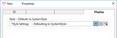
Serial Port properties Display tab
When this tag is represented on screen by widgets that can use a Style Settings tag, you can save development time by choosing the Style Settings tag that holds the correct display configuration for this tag instance.
The default configuration will use System Style, the default style tag that is automatically part of every new VTScada application.
The following widgets are available to display information about your application’s Serial Port tags:
