
Pangnirtung is an Inuit hamlet in the Canadian territory of Nunavut, located on Baffin Island. Situated on the coast of the Pangnirtung Fjord, which eventually merges with Cumberland Sound, the Inuit and their ancestors have inhabited the area for thousands of years.
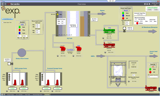
Fredericton based integrator, exp Services Inc., was selected for the nine million dollar renovation of Pangnirtung’s secondary municipal wastewater treatment facility. They chose VTScada for the brand new Supervisory Control and Data Acquisition (SCADA) system which gives the operators the ability to monitor and control the plant, receive alarms and notifications, view historical data trends and report. VTScada communicates with a total of three Allen Bradley Compact logic PLCs over a plant Ethernet network.
Dwaine Brewer, Mechanical Technologist at exp Services Inc.*, has this to say about their first installation with VTScada “VTScada was very user friendly to configure and the technical support was always eager to assist.”
Along with the new control system, the upgrade included the addition of a packaged membrane bioreactor system with aeration and anoxic biological treatment tanks to provide the bulk of the treatment. A number of additional processes and process units were required to form the complete wastewater treatment system for the Hamlet. VTScada monitors and controls such treatment plant processes as described below.
Screening – Preliminary treatment consists of coarse and fine screening. All wastewater initially flows through the coarse screen and into the first of two wastewater sumps. The wastewater is then pumped through a drum screen with a screen element having 2 mm openings. The screened wastewater then flows to a second sump where it is pumped to the Equalization Tank.
Screened material collected from the drum screen is washed, compacted and dewatered prior to being discharged into a bagging collection system. Screened material from the coarse screen is collected in a separate lined bin. All screenings are ultimately disposed of in the solid waste landfill site.
Pumping – A review of the existing pumps was completed during the detailed design phase and determined that the performance capabilities, current condition, and projected service life, were adequate for the upgraded facility.
Pumping of the raw wastewater is required to first move the raw wastewater from the initial receiving sump (via a duplex submersible pump system) through the drum screen. A second duplex submersible pump system then transports the wastewater from the screening area to the equalization tank.
From the equalization tank, raw wastewater is fed to the biological treatment system using duplex, centrifugal, end-suction pumps that are located on a concrete housekeeping pad on the building floor near the equalization tank. These pumps are controlled by variable frequency drives to allow for steady inflow to the biological system (anoxic tank). These pumps were designed for continuous duty operation to allow for consistent inflow to the biological system over a 24 hour period.
A duplex pump system extracts permeate (treated effluent) from the membrane system. These pumps both operate as duty pumps with one pump dedicated to each membrane tank. These pumps are rotary lobe pumps with VFD control to allow for precise flow control.
Additional pumps provide a constant recycle of Mixed Liquor Suspended Solids (MLSS) from the membrane tanks to the anoxic tank. The discharge piping from these pumps is configured to allow for a portion of the recycled MLSS to be diverted to the sludge storage tank for wasting. A hose pump is utilized to transfer sludge from the storage tank to the dewatering system and is operated/controlled by an integral speed control system. The recycle pumps (centrifugal, end-suction pumps) are VFD controlled to allow variation of the recycle flow rate.
Equalization – The existing equalization (EQ) tank was incorporated into the upgraded system to absorb the peak flows associated with the trucking of wastewater over an 8 hour period. The EQ tank provides attenuation within the system to help promote a steady delivery of flow and organic loading to the downstream biological treatment system. Sharp spikes in either flow or organic load can lead to instability and reduced treatment performance within any biological system and an EQ tank helps to minimize these potential impacts. The existing EQ tank has a total volume of approximately 189 m3; the usable volume is in the order of 138 m3.
Previously screened wastewater will be pumped from this tank to the MBR system. The tank will generally operate at its lowest level in order to have containment volume available when needed. This tank is equipped with a diffused aeration system that can be used to prevent the tank contents from going septic and causing odours.
Membrane Bioreactor (MBR) – The MBR provides the majority of the wastewater treatment. The biological treatment system consists of three main zones, identified as the anoxic tank, the aeration tank and the membrane tanks. The anoxic tank is the first zone in the process and consists of a mixed tank with relatively low levels of dissolved oxygen (DO). Bacteria in the presence of low oxygen levels are able to perform biological nitrogen removal (which also can reduce the amount of chemical required for alkalinity addition). The aeration tank follows the anoxic tank and it is here that most of the biological treatment occurs within the system.
The aeration tank operates at a higher DO concentration allowing the aerobic bacteria to consume the organic material in the wastewater, eliminating most of the influent BOD5 concentration. It is in the aeration tank that the ammonia nitrogen is converted to nitrates and nitrites (through the process of nitrification) thereby reducing the potential for ammonia toxicity within the receiving waters (Pangnirtung Fiord) at the point of the effluent discharge. The mixed liquor from the aeration tank flows to the membrane tanks.
Some organic removal continues within the membrane tanks but the primary purpose is to house the submerged membranes that provide virtually 100% removal of TSS from the effluent. Dual membrane tanks allow for one tank to be out of service for periodic membrane cleaning as required without a need to stop flow to the system.
Ultraviolet (UV) Disinfection – A final step in the treatment process is UV disinfection for deactivation of pathogens within the effluent discharged from the membrane system. A stainless steel channel bolted to the floor houses the UV light bulbs that perform the pathogen deactivation. The UV system includes an outlet weir to maintain a minimum level of treated effluent in the channel. This minimum level ensures that the bulbs are always submerged even under low flow conditions. The UV system includes provision in the piping configuration, including valves, to allow for bypass of the system when maintenance is required. An additional advantage of the high quality effluent produced from the membrane system is that the effluent has a high UV transmittance which can allow for the use of a smaller UV system to achieve the same effectiveness.
For More Information contact: Steve Love 506-452-9000, steve.love@exp.com
About exp Services Inc. – With a mission to understand, innovate, partner and deliver, exp provide professional, technical and strategic services to the world’s built and natural environments in six key practice areas: Buildings, Earth & Environment, Energy, Industrial, Infrastructure, and Sustainability. Our heritage dates back to 1906, when the earliest of exp’s predecessor companies started its engineering infrastructure practice in northern Ontario. Today, close to 3,000 creative exp professionals across North America and around the globe provide the expertise and experience needed to deliver successful projects for clients. http://www.exp.com/en/home/
*Dwaine Brewer has since changed positions since this case study