
Not counted towards your tag license limit.
Data Flow RTU drivers are used to provide an interface to a Data Flow RTU. Each Data Flow RTU driver provides for up to 18 installed Data Flow modules.
Data Flow RTU driver tags do not require polling drivers because they have their own polling features.
Driver Errors: To learn more about the cause of an error condition, refer to the Driver Summary Report and the Driver Error Report, both of which are available in the Reports page. The Show Stats button will also provide current and last error messages: Show Statistics Button Widget
Reference Notes:
Operators who do not have configuration privileges, but do have either "tag modify" or "manual data" security privileges can toggle the active polling state on or off if this tag is drawn as a Comm Indicator on a page. When the operator right-clicks on the Comm Indicator for the driver, a context menu will open, allowing the Active status to be changed.
When data is written to a Data Flow tag, it is immediately passed to the integrated Polling Driver tag and then on to the associated communication driver tag. Following each write, all I/O addresses will be read immediately so that feedback need not wait for the next polling cycle.
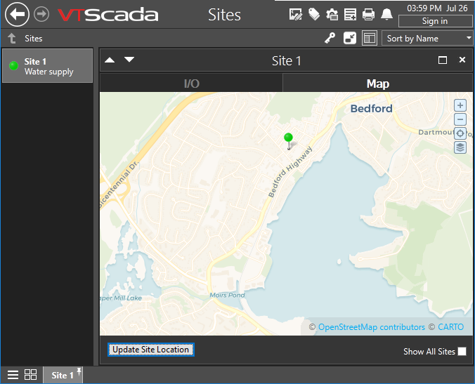
The Data Flow RTU driver can be represented on a Site Map.
Alarming
When polling fails-over from the primary server to a backup, VTScada automatically generates an alarm with priority 3 (warning). You can control this using application properties as follows:
- BackupSwitchCount. Defaults to 30. The number of consecutive communication errors that need to occur when polling Data Flow RTUs before switching to the first specified backup server.
- PollDriverAlarmDisable. Defaults to FALSE. In spite of the name, this property will decommission the alarm rather than disable it when set to TRUE.
- PollDriverAlarmOnDelay. Defaults to 60 seconds. Avoids nuisance alarms from transient network issues.
- PollDriverAlarmPriority. Defaults to 3 - Warning. Legacy applications may use the property BackupAlarmPriority for the same result.
Data Flow RTU Driver properties ID tab
The Data Flow RTU Driver type includes one extra field on the ID tab: The Station number, (also known as the RTU address) and the Digipeat route.
DFS stations can digitally repeat (digipeat) information to work around obstacles that block direct signals. Refer to the

The ID tab of every tag includes the same common elements: Name, Area, Description, and Help ID.
Name:
Uniquely identifies each tag in the application. If the tag is a child of another, the parent names will be displayed in a separate area before the name field.
You may right-click on the tag's name to add or remove a conditional start expression.
Area
The area field is used to group similar tags together. By defining an area, you make it possible to:
- Filter for particular tag groups when searching in the tag browser
- Link dial-out alarm rosters to Alarm tags having a particular area
- Limit the number of tags loaded upon startup.
- Filter the alarm display to show only certain areas.
- Filter tag selection by area when building reports
When working with Parent-Child tag structures, the area property of all child tags will automatically match the configured area of a parent. Naturally, you can change any tag's area as required. In the case of a child tag, the field background will turn yellow to indicate that you have applied an override. (Orange in the case of user-defined types. Refer to Configuration Field Colors)
To use the area field effectively, you might consider setting the same Area for each I/O driver and its related I/O tags to group all the tags representing the equipment processes installed at each I/O device. You might also consider naming the Area property for the physical location of the tag (i.e. a station or name of a landmark near the location of the I/O device). For serial port or Roster tags, you might configure the Area property according to the purpose of each tag, such as System or Communications.
You may define as many areas as you wish and you may leave the area blank for some tags (note that for Modem tags that are to be used with the Alarm Notification System, it is actually required that the area field be left blank).
To define a new area, type the name in the field. It will immediately be added. To use an existing area, use the drop-down list feature. Re-typing an existing area name is not recommended since a typo or misspelling will result in a second area being created.
There is no tool to remove an area name from VTScada since such a tool is unnecessary. An area definition will exist as long as any tag uses it and will stop existing when no tag uses it (following the next re-start).
Description
Tag names tend to be brief. The description field provides a way to give each tag a human-friendly note describing its purpose. While not mandatory, the description is highly recommended.
Tag descriptions are displayed in the tag browser, in the list of tags to be selected for a report and also on-screen when the operator holds the pointer over the tag’s widget. For installations that use the Alarm Notification System, the description will be spoken when identifying the tag that caused the alarm.
The description field will store up to 65,500 characters, but this will exceed the practical limits of what can be displayed on-screen.
This note is relevant only to those with a multilingual user interface:
When editing any textual parameter (description, area, engineering units...) always work in the phrase editor. Any changes made directly to the textual parameter will result in a new phrase being created rather than the existing phrase being changed.
In a unilingual application this makes no difference, but in a multilingual application it is regarded as poor practice.
Help Search Key
Used only by those who have created their own CHM-format context sensitive help files to accompany their application.
Station Number(, RTU Address), Digipeat Route
The address of the destination station is first, followed by the station addresses of the RTU it passes through. For example, if you want to talk to station 3 through station 5, this field would be
3, 5
The RTU address is shown in brackets because the station number and RTU address can be different. (This is not common, but it does happen.) In this case, the station number is arbitrary and the RTU address configured on the device is the one to use.
Data Flow RTU Driver properties I/O tab
The I/O tab for a Data Flow RTU driver tag provides properties that can be used to establish a connection between this tag and the physical Data Flow RTU.

Serial Port Name
To connect to this port with VTScada, you can use one of several different hardware solutions:
- Serial port cable connected directly.
For this case, configure and select a Serial Port tag.
- Stand alone serial modem connected to the serial port on the radio.
VTScada has its own modem that is used to dial up the modem connected to the unit. For this option, configure and select a serial port that is using a modem.
- Ethernet terminal server connected to the serial port on the unit.
VTScada is connected to the same network as the terminal server and can connect to it with either a TCP/IP or UDP/IP port tag
Any type of VTScada port tag may be used, but it must match the hardware connection to the unit.
Poll Interval
Enables you to set the amount of time (in seconds or in fractions of a second) between polls of the physical Data Flow RTU.
Note: If the Active check box is not selected, the associated Data Flow RTU will not be polled, regardless of the interval assigned in the Poll Interval (Sec) field.
Active
Specify whether the designated poll interval is active or idle.
If the Active check box is selected, the associated Data Flow RTU will be polled according to the interval assigned in the Poll Interval field.
If the Active check box is not selected, the associated Data Flow RTU will not be polled, regardless of the interval assigned in the Poll Interval field.
The active status can also be toggled by the operator if the tag is drawn as a Comm Status indicator. Right-clicking on that widget will open a menu with which the operator can change the active status. When drawn as a SiteDraw, the outer ring will turn purple when the driver is not active.
No Response Time Limit
Set the amount of time (in seconds or in fractions of a second) that VTScada will wait when an attempt to poll the Data Flow RTU has been made.
If no communication is made, the system will attempt to poll the station again, according to the setting in the Retries spin box. If the system is unable to poll the Data Flow RTU, the next RTU in sequence will be polled.
Retries
The number of times to retry a message before declaring an error.
Use only if the driver is connected to a device that uses a serial port or a UDP/IP port that is configured to be polled. When connected directly to a device using TCP/IP, this value should normally be set to 0 since TCP/IP is a guaranteed message delivery protocol.
For unreliable communications, such as radio, set to 3 or 4.
Full Refresh Time
Enter a number indicating the amount of time, measured in hours that the system should wait before doing a full refresh of data values from the Data Flow RTU.
Hold Values on Error
Specify whether data should be held in the event of a communications error with the Data Flow RTU.
If the Hold Values on Error check box is selected, the last received value from the Data Flow RTU will be retained otherwise, the data will be invalidated on error.
Group Poll Supported
Select this box to specify whether the Data Flow RTU represented by this tag belongs to a poll group (if group polling is supported by the radio interface module).
Service Port Connection
If selected, The service port enables communication with the RTU via serial devices (such as Lantronix). It is an alternative to using the DataFlow RIM card radio. The DataFlow protocol is slightly different through the service port. Minor differences will be observed, such as all responses being marked as station '0' and the absence of CRCs on messages that would otherwise have them.
Echo
Used if the Service Port Connection option has been selected. Enable or disable according to whether your device transmits an echo for each transmit operation.
Read RIM Analog Values
When selected, the driver will query the Radio Interface Module (RIM) for changes in analog values. Note that this is not supported by all Radio Interface Modules. Defaults to FALSE (unselected).
Data Flow RTU Driver properties Modules tabs
The Modules tabs of the Data Flow RTU driver tag properties folder enables you to select existing (or create new) Data Flow module tags to represent the Data Flow modules installed for this RTU (see Data Flow Module Tags). You may associate up to 18 Data Flow module tags with one Data Flow RTU driver.
The modules are divided between the tabs, Modules A-F, Modules G-L and Modules M-0.

Module A, B, etc.
Use the Module fields to identify which module installed at a physical RTU by selecting a Data Flow module tags.
To associate this tag with a set of Data Flow module tags, click the drop-down field to select the appropriate Data Flow module tag for each module.
Data Flow RTU Driver properties Location tab
The Location tab is used to define the placement (latitude and longitude) of the DataFlow station. Decimal values should be used rather than degrees, minutes and seconds.
You may find it easier to set the location using the map interface than to enter the latitude and longitude values here.
Latitude and Longitude
Holds location coordinates for this tag, thereby allowing it to be represented on a Site Map page.
Custom Details Page
If a custom details page has been created for this context tag, then that page should be selected here. If there is no custom details page, then operators will see the standard Site Details page upon clicking the pin for this tag in a Site Map.
Advanced Configuration:
The default page selection dialog has a filter for "all pages" or "site pages", meaning those that take a site tag as the first parameter.
You can add either of the following two properties in the Edit Properties page of the Application Configuration dialog to restrict this filter:
LimitPageListToSitesPages
System section. Set to 1 (TRUE) to prevent access to the "all pages" option in the page selection dialog for all users.
LimitPageListToSitesPagesIfRealmUser
System section. Set to 1 (TRUE) to prevent access to the "all pages" option in the page selection dialog if the user belongs to a security group.
Custom Map Icon
If a custom map icon widget has been defined, you can select it here. That icon will then be used instead of the standard pin when this tag is represented on a Site Map page. If there is no custom map icon, then the standard pin will be used.
Site List Display
Assuming that this tag has site properties, it will be included in the list of a Sites page. What will happen when an operator clicks on this tag in that list depends on the Site List display choice, and on whether any of this tag's children are I/O tags.
- Display as Site: A click will open the Site Details page as a pop-up.
- Display as Folder: A click will leave focus on the Sites page, but the list will now show the child tags of this site.
- Exclude: This tag should not be shown in the Sites page list.
Map Zoom Level
If Automatic is chosen (the default) then when a map is opened, showing only this site, it will zoom to level 15, which shows only the immediate surroundings. You may select any value between 18 (the closest possible level) and 2 (showing the entire globe).
Default zoom level.
The following widgets are available to display information about your application’s DataFlow RTU tags:
Enable Polling Checkbox Widget
