
Counted towards your tag license limit.
This is a legacy tag type. You are advised to use the I/O and Calculations Tag instead.
Use this legacy type only if you are certain that it contains unique features that are absolutely necessary to your work.
Analog Control tags are used to write values to equipment. While an Analog Status tag can also write a value, the Analog Control tag will give you more tools and options.
Unlike a Digital Control tag, the value of an Analog Control will reflect the last value written. It will also retain that value across application restarts, which is something that a Digital Control tag does not do. But, this value can be misleading if there are alternative means of control such as PLC programming or direct operation of equipment. If possible, it's always worthwhile to have an Analog Status tag that reads the actual state of the equipment being controlled and use that to provide feedback to the Analog Control for display purposes. In all but the most rare circumstances, this feedback should be used only to update the displayed value of the Analog Control.
Analog Control tags need a scaling factor for exactly the same reason as an Analog Status tag. With regard to scaling, they differ in only two ways: there is no option to set a display scaling and there is no deadband.
Retained or Persisted values
Analog Control and Analog Output tags will both retain their last written value across application restarts. Use these tags when there is a need for a value to persist.
String I/O tags with output enabled, and with no driver ("No tag selected" rather than the default, "[*Driver] None found") will retain their last written value across application restarts.
The Digital Control and Digital Output tags do not have a similar feature, but an analog tag can be used in their place, writing a zero or a one. If the intent is to write a clear zero or one with an analog tag, both the scaled and unscaled range should be adjusted for a minimum value of zero and a maximum value of one, so that scaling does not adjust the values.
Record Operator-Entered Values:
While the output tags are designed to write to a device, they can also be used to record purely operator-entered values. For example, an operator may be asked to read a value from a device that is not connected to the automation system and record that value in a place where it can be included in the SCADA system's reports.
To record operator-entered values:
- Create an Analog Control tag.
The name and description should match the information that is to be recorded.
Do not configure an I/O device or address.
Ensure that the scaled minimum and maximum values allow the full range of expected numeric values. (The Operator Notes page exists to record text.) - Add a Logger tag to the Analog Control.
Select the option, Log on Change as well as Time.
Set the Log Range Interval to a very large value (for example, 3153600000 == 100 years). This ensures that a value will be written to the Historian only upon operator entry. - Draw the Analog Control tag on a page as a Numeric Entry widget, having a relevant label. Operators should note that it is necessary to press enter, or tab away from the data entry field before the value will be saved.
Each time the operator enters a new value, it will be written to the Historian, and may be used in trend graphs and reports. Note that a click on any widget linked to an output tag does not open the trend window.
The ID tab of every tag includes the same common elements: Name, Area, Description, and Help ID.
Name:
Uniquely identifies each tag in the application. If the tag is a child of another, the parent names will be displayed in a separate area before the name field.
You may right-click on the tag's name to add or remove a conditional start expression.
Area
The area field is used to group similar tags together. By defining an area, you make it possible to:
- Filter for particular tag groups when searching in the tag browser
- Link dial-out alarm rosters to Alarm tags having a particular area
- Limit the number of tags loaded upon startup.
- Filter the alarm display to show only certain areas.
- Filter tag selection by area when building reports
When working with Parent-Child tag structures, the area property of all child tags will automatically match the configured area of a parent. Naturally, you can change any tag's area as required. In the case of a child tag, the field background will turn yellow to indicate that you have applied an override. (Orange in the case of user-defined types. Refer to Configuration Field Colors)
To use the area field effectively, you might consider setting the same Area for each I/O driver and its related I/O tags to group all the tags representing the equipment processes installed at each I/O device. You might also consider naming the Area property for the physical location of the tag (i.e. a station or name of a landmark near the location of the I/O device). For serial port or Roster tags, you might configure the Area property according to the purpose of each tag, such as System or Communications.
You may define as many areas as you wish and you may leave the area blank for some tags (note that for Modem tags that are to be used with the Alarm Notification System, it is actually required that the area field be left blank).
To define a new area, type the name in the field. It will immediately be added. To use an existing area, use the drop-down list feature. Re-typing an existing area name is not recommended since a typo or misspelling will result in a second area being created.
There is no tool to remove an area name from VTScada since such a tool is unnecessary. An area definition will exist as long as any tag uses it and will stop existing when no tag uses it (following the next re-start).
Description
Tag names tend to be brief. The description field provides a way to give each tag a human-friendly note describing its purpose. While not mandatory, the description is highly recommended.
Tag descriptions are displayed in the tag browser, in the list of tags to be selected for a report and also on-screen when the operator holds the pointer over the tag’s widget. For installations that use the Alarm Notification System, the description will be spoken when identifying the tag that caused the alarm.
The description field will store up to 65,500 characters, but this will exceed the practical limits of what can be displayed on-screen.
This note is relevant only to those with a multilingual user interface:
When editing any textual parameter (description, area, engineering units...) always work in the phrase editor. Any changes made directly to the textual parameter will result in a new phrase being created rather than the existing phrase being changed.
In a unilingual application this makes no difference, but in a multilingual application it is regarded as poor practice.
Help Search Key
Used only by those who have created their own CHM-format context sensitive help files to accompany their application.
Analog Control properties I/O tab
In the I/O tab, you will find the properties used to identify and establish a connection to the communication driver tag being used to exchange data with your physical I/O device (e.g. PLC or RTU), or to the polling driver responsible for determining the order and rate at which data polls will occur.
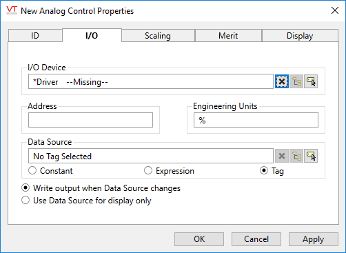
I/O Device
Select the communication driver tag from which data will be read.
By default, the tag will look for a parent tag that is a device driver (*Driver). If none is found, the text "--Missing--" will be displayed. The tag button to the right of the field opens the tag browser, from which you can either select an existing communication driver tag or add a new one. The X button will clear the field. Right-clicking on a tag in the field will open a dialog with which you can add or remove a Snapshot Expression or open a selected driver's properties dialog.
Address
Provide the address within the I/O device to which this tag is to write data. This value must match the configuration of your PLC or RTU hardware. Refer to the Addressing topic for your particular device driver for guidance.
For some drivers (SNMP and the OPC Client) an address browser is provided to assist you.
Engineering Units
Provide units of measure that the input data represents. Possible values for this field include "rpm" "degrees C", "%", etc
Data Source
[Optional] While Analog Control tags usually take their value from an operator-controlled drawing object, the Data Source field provides the option of configuring this tag to accept a value from another tag or expression instead.
The value from the Data Source can be written to the I/O device, or it can be used to simply update the widget display.
If you have selected a data source that is configured to write output and have also drawn the tag as an object that operators can use to set values, then both can write to the I/O device. The value written will be whichever was most recently changed.
Write output when Data Source changes
When selected, the value supplied by the data source tag or expression will be written to the I/O device and will also be used to set this tag’s value. Selecting this option automatically deselects the "Use Data Source for display only" option.
Use Data Source for display only
When selected, the value supplied by the data source tag or expression will not be written to the I/O device but will be used to set this tag’s value. Selecting this option automatically deselects the "Write output when Data Source changes" option.
Analog Control properties Scaling tab
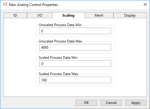
The Scaling tab is used to convert scaled data (intelligible to operators) into unscaled, raw data for the I/O device. VTScada uses an algorithm to calculate this tag's value internally, based on the known unscaled and scaled values you supply.
The default value for each of these fields is stored in an application property. You are advised to change those properties to match the values used by your hardware by using the Edit Properties page of the Application Configuration dialog.
You will need to use the Advanced mode of the properties page. The properties to copy and edit are:
- AnalogUnscaledMinDefault
- AnalogUnscaledMaxDefault
- AnalogScaledMinDefault
- AnalogScaledMaxDefault

|
VTScada assumes a linear relationship between the values as shown. The scaled and unscaled process values you provide set the slope of the line, allowing any value on one axis to be mapped to the other. The values do not limit what the tag can read, but the Scaled Process Min and Max values do limit what the tag can write. |
Min and Max Unscaled Process Data (Required.)
Use these to tell VTScada the range of raw values to expect from or write to hardware.
Min and Max Scaled Process Data (Required.)
Values must correspond to the Unscaled Min and Max values. VTScada uses these to convert between engineering units displayed in the SCADA system and raw values read from or written to hardware.
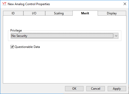
Analog Control properties Merit tab
Privilege
Select a custom security privilege
Questionable Data
Use the Questionable Data parameter to flag this tag’s data in the event that you suspect the values it is reporting might not be accurate, or when this tag has initially been created and you wish to ensure that its data is marked for extra monitoring.
Analog Control properties Display tab
Style
When this tag is represented on screen by widgets that can use a Style Settings tag, you can save development time by choosing the Style Settings tag that holds the correct display configuration for this tag instance. (See: Style Settings Tags)
The default configuration will search for the first parent tag of the Style Settings type. If there is none, it will use System Style, which is the default style tag that is automatically part of every new VTScada application.
Display Order
Used to specify the placement of this tag when viewed in an associated station dialog. See Order tab for further details.
The following widgets are available to Analog Control tags:
Confirmation Prompts for Output Tags - Control options for confirmation prompt text.
